Review Article - (2013) Volume 2, Issue 5
Computer modelling techniques and Rapid Prototyping (RP) technologies can be used to enhance applied medicine. This paper decribe the use of these methods to develop computer and physical models which are used to plan and support different surgical treatments such as complex fractures, tumours, maxilla traumas and malformations. This present work reviews the use of segmentation techniques and modelling for planning maxilla facial surgery and particularly to support the treatment of retrognathia which is a malformation where the maxilla or the mandible is further posterior than normal. The surgical process in use to correct this malformation is called distraction osteogenesis. It involves gradual, controlled displacement of surgically created fractures which results in simultaneous expansion of soft tissue and bone volume. The procedure of mandibular osteogenic distraction involves sectioning cortical bone at the site of distraction. The distraction device (the distractor) is mounted on either side of the jaw. The distractor either may be attached directly to the bone or may be partially tooth borne. Gradual distraction is then performed at a rate of 1-2 mm/day, which is done incrementally. Distractors, for intraoral use, have been developed to eliminate extra oral scars. It is complicated and frustrating to position and manipulate these devices during surgery.
The use of rapid prototyped models makes the operation easier and more accurate; indeed it is possible to adjust the distractor on the physical model and use the device directly on the patient after sterilization. Moreover pre operative preparation reduce the possibility of damaging the nerve canal during osteosynthesis since the direction of distraction is decided on the model.
Keywords: Three-dimensional reconstruction, Medical modelling, Rapid prototyping, Intraoral distraction
3D Models (3DM) and Rapid Prototyping (RP) technologies increase efficiency in applied medicine and particularly in supporting planning in complex surgery.
In principle RP technique allow the computer screen image to be accurately reproduced in a few hours as an acrylic model which can be handled by the surgeon, allowing an immediate and intuitive understanding of the most complex 3-D geometry and can be used to accurately plan and practice an awkward operative procedure [1].
RP isn’t a new process, it was introduced in the 1980’s to define new techniques for the manufacturing of physical models and was originally introduced in industry to improve design and reduce product development time. Applications in medicine of RP technologies as support for surgical planning are seen already in 1994 [2].
The development and use of this methodology has been rapidly growing hand in hand with the technological improvement and high resolution achieved by medical modalities such CT and MRI scan. The RP technology available today allows building of a medical model layer by layer, and it is able to reproduce almost every form of the external and internal anatomic structure if medical data are properly processed.
The medical field which has mainly benefiting from the use of 3DM and RP is the Cranio Maxillofacial (CMF) surgery, the development has mainly been over the last fifteen years [3] defining new processes for designing, prefitting and production of surgical implants. The main benefits for using RP models include improving surgical planning, enhancing diagnostic quality, decreased exposure time to general anaesthesia, decreased blood loss and shorter wound exposure time [4].
Today 3DM and RP techniques are widely employed to support planning in different types of surgery especially involving mandible malformation or defects such as bilateral sagittal split osteotomies [5] or chin repositioning by pre-bending titanium plates on the printed model [6]. RP models have also been used to support customisation of distractor fixation plates in complex craniofacial malformations [7], in mandibular resection for the design of the reconstructive plate [8] and in mandibular reconstruction using bone plates and bone grafts [9].
Furthermore, 3DM and RP techniques are often used to for repairing orbital floor fractures using pre-shaped titanium mesh implants based on 3D models of unaffected orbit which are mirrored onto the injured orbit [10].
However, most literature concerning use of 3DM and RP to support medicine and surgery is comprised of reports of single case studies that describe a given technology or application [4]. There are not yet in literature any report or published paper which describes an integrated service based on RP and 3DM processes with the goal of supporting clinical applications With the aim of improving our healthcare, reducing future costs and developing more thorough clinical guidelines to aid surgical planning and assessment, in 2007 at National University Hospital of Iceland Landspitali an in-house service for 3DM and RP have been established allowing physicians and surgeons from different specialities to submit requests for RP models and receive it within 24 hours. This process was also employed in research activities to study anthropometry of human muscle [11] and in preparation for complex brain surgery in combination with neurosurgical navigation systems [12].
This paper describes the work process, the organization and the benefits of establishing a Hospital RP service with special focus on maxillofacial applications.
Integrated medical modelling sevice (IMMS)
The process the combine use of medical scan data, processing and reconstruction of 3D models and rapid prothotyping is defined as Medical modelling [13].
The process involves capturing human anatomy data with the appropriate medical modality, processing the data to isolate individual tissue or organs using special image processing software and print the physical model with a rapid prototyping technology.
Since 2007 at National University Hospital of Iceland Landspitali we have developed an integrated medical modelling service (IMMS) to provide RP models for different medical purposes with the aim of optimizing the clinical processes. The fundamental steps to implement such medical modelling service are summarized in Table 1.
| Steps | Actions to implement the IMMS |
|---|---|
| 1 | Select the optimal medical modality to provide best visualization of the anatomical structure of interest (CT or MRI) |
| 2 | Set the appropriate scanning protocol for the region of interest |
| 3 | Retrieve the scan data from the Hospital PACS |
| 4 | Import the scan data to a medical image processing software and segment the region of interest |
| 5 | Import the segmented model to 3D Print software and start printing |
| 6 | Deliver the model to clinical personnel |
Table 1: Main Steps implementing the IMMS.
The IMMS is based on a synergetic cooperation between clinicians and biomedical engineers and optimized access to medical data. The block diagram of Figure 1 shows the organization for the IMMS with the information flow between engineers and clinicians in routine cases. The Biomedical Engineers receives request (type of model and patient ID) from the clinical personals through email or by direct phone. For routine models; medical modality, scanning protocol and type of modelling are already established. The scan data are available on the Hospital PACS system and accessible through the Brilliance Workspace Portal [14]. The DICOM series are imported into medical image processing software called MIMICS [15] where the segmentation of the region of interest is performed. The 3D model is converted into a printable format called STL and sent to a 3D printer [16]. Finally the RP model is delivered to surgeons and used for the specific application. The whole process is completed within 24 hours, without delaying scheduled surgeries, which are usually planned at least with 1 week in advance.

Figure 1: Integrated medical modelling sevice block diagram and information flow.
In non-routine cases doctor and engineers plane together step 1 and 2 (Table 1) and interact during the preparation of the model (segmentation work). In these cases the medical modelling process may take up to 1 week to be ready.
Medical scan protocol
To enable image segmentation and following rapid prototyping of anatomical model we set some minimum requirements for the scanning parameters.
- For CT scans: Image matrix 512×512 pixels, pixel size below 0,8 mm slice increment below 1 mm.
- For MRI scans: Image matrix 256×256 or 512×512 pixels, pixel size below 1 mm slice increment below 1.5 mm.
IMMS for Mandibular Distraction Osteogenesis (MDO)
In this work medical modelling methodologies are applied to plane and organize surgical process for reconstruction of skeletal deformities in the maxilla using distraction osteogenesis technique. This technique involves gradual, controlled displacement of surgically created fractures which results in simultaneous expansion of soft tissue and bone volume. In the case in mandible advancement it is the latest method after decades with traditional sagittal split osteotomy. These devices for intraoral use, have been developed to eliminate extra oral scars are complicated to position and manipulate during surgery. Adjusting the distractor and positioning is frustrating and takes time during surgery.
The MDO procedure involves sectioning cortical bone at the site of distraction. The distraction device is mounted either side of the jaw. This may be attached directly to the bone or may be partially tooth borne. Gradual distraction is then performed at a rate of 1-2 mm per day, which may be done incrementally. Osteogenic distraction can be carried out by the clinician on an outpatient basis or by the patient at home.
In order to isolate bones from other tissues and visualize the mandibular nerve within the jaw, CT scan data are imported into a special image processing and editing computer program called MIMICS [15]. In this software environment, the 3D form of anatomy can be reconstructed in 3D and certain regions of interest isolated and also modified.
The main IMMS purpose is to allow planning of MDO procedure using RP models which display the mandibular nerves.
CT scanned objects are coded in the Hounsfield scale which is a quantitative scale for describing radio density. Different HU values are ascribed to air, water, fat, bone and muscle. To isolate bone from soft tissue a threshold based on the HU values is defined. In the thresholding process the individual pixels are marked if their value is included in a certain HU interval. Therefore the first of five steps is to create a model is establishing a proper threshold and remove possible metal artefacts as seen in (Figure 2A and B). The HU interval used in this application is [300, 3000] HU. The second step is to reconstruct in 3D the maxilla bone and jaw as it is showed in Figure 2C.

Figure 2: (A) Thresholding in the interval [300, 3000] HU. (B) Artefact removed. (C) 3D reconstruction of jaw and maxilla.
The third step is to render visible the mandibular nerve within the jaw. The mandibular nerve is the largest of the three branches of the trigeminal nerve which are responsible for sensation in the face. It is very important to preserve its integrity during the operation. The nerve passes within the lower jawbone through the cavity visible on the maxilla cross-section (Figure 3A). A special segmentation tool called “dynamic region growing” and based on the connectivity of gray values is used to visualize the nerve into the jaw cavity. The result is showed in Figure 3B.

Figure 3: (A) Mandibular nerve pattern; Cross section. (B) 3-dimensional representation.
The fourth step is to modify the jaw in order to allow the visualization of the mandibular nerve. Using special editing tools a section of the jaw cortical bone is removed in proximity of the nerve channel (Figure 4A). This operation is repeated on every cross section where the nerve is visible obtaining as results the new 3D model of the jaw (Figure 4B).

Figure 4: (A) Visualization of mandibular nerve: on the cross section. (B) 3-Dimensional reconstruction.
The final step is to RP the model. We use 3-D printing technologies [16] because are more reliable and economic compared to other available techniques [17].
The 3D models are built layer by layer and layer thickness can be set down to 0.25 mm. The printing speed is between 2, 4 layers per minutes and total printing time for an adult maxilla is between 4 to 6 hours. The total printing cost depends from the model size; for a maxilla can oscillates between 150 and 200 euro which added to the engineering work and associated cost for software and facilities, give as total cost approximately 400 euro per model (Figure 5).

Figure 5: RP model used in surgery for the evaluation and planning of MDO. The 3D-model displays the mandibular nerve within the bone. The model is used for treatment planning and to bend the distractor device directly on the physical model of the previous surgery.
The IMMS was established in 2008; different clinical applications have been benefiting from this service, though the most successful application is the MDO planning with over 50 operations planned during these years (Figure 6).

Figure 6: Clinical cases and applications performed through the IMMS.
For the MDO treatment, RP models are delivered to the surgeon 1-2 days before the operation. The 3D model is used for pre-banding the distractor before surgery as seen in Figure 7. In this way operation time reduces of 25% up to 35%.

Figure 7: Banding the distractors device on the model before operation.
Moreover the model is used during the surgery (kept in a sterilized plastic bag) to measures and control distance bone-nerve and jaw thickness.
IMMS: Economic Assessment in MDO treatment
The calculation of the benefit of 3D-modelling is focused on the time saving in all areas in the hospital process. Based in the time reduction the cost reduction can be calculated. The break-even is calculated to assess when the 3D modelling is profitable.
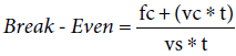
Where: fc=fixed costs, vc=variable costs/surgery, vs=variable savings/surgery and t=number of surgeries
Figure 8 summarizes the Break-Even analysis showing that by planning 32 surgeries per years the rapid prothotyping service would be profitable for the Hospital.

Figure 8: Saving-Cost comparison and Break-Even analysis *saves time in preparation of instruments, costs time in preparing surgery, ** around 1/3 of time.
In addition to these numbers there are facts which cannot be quatified yet such us reduction of hospitalization, avoiding correction surgery and prevent patients from going into unnecessary surgeries (expecially in orthopedic surgeries); these additional benefits would further decrease the number of surgeries to reach the Break-Even.
Distraction osteogenesis, also called callus distraction, is a surgical process used to reconstruct skeletal deformities and lengthen the long bones of the body and by that soft tissue nerve and muscular tissue adapt to the lengthening [18,19].
The most common complication is nerve injuries and has a wide range depending of the patient age [20]. Distraction osteogenesis has reduced nerve injuries dramatically [21]. Complications following traditional sagittal split osteotomy compared to MDO showed a lower incidence of persistent inferior alveolar nerve disturbance (2.9%) and condylar resorption (1.4%) compared with Bilateral Sagittal Splitt Osteotomy (BSSO) patients, in whom the incidence of these conditions was 27.8% and 6.1% [22]. The disadvantage of DO is longer operation because the device has to be adjusted and positioned correctly. Using RP models accuracy in positioning the distractor is improving. In our experience by using 3D models the operation is much simplified as manipulation with the distractor is eliminated during the surgery and the direction of distraction is decided on the model reducing also the possibility of damaging the nerve canal during osteosynthsis. Operation time for MDO treatment is reduced at least of 40-50 minutes [11]. In addition the model improves patient’s education and compliance.
Other types of maxillofacial surgery are starting to utilize IMMS since the physical model helps the surgeon’s to sense the 3rd dimension not provided with the conventional medical image. Finally the 3D models have also been of value in the post-operative assessment by providing valuable reference for continuing education in challenging maxillofacial cases and multiple surgical treatments.